MSDI212 - HD / SDI 1080P Slip Rings
MSDI212 slip ring ‘ler HD-SDI küçük ve kompakt yapılı slip ring'ler olup,
24.8mm dış çaplı * Uzunluk 29.6mm, standart, satışa hazır, stokta mevcut bulunan slip ringlerdir.
1080P vidyo iletimi için özel olarak tasarlanmışladır.
RG-179,75 ohm, frekans değeri, DC-2.3GHz'e kadar çıkabilir.
- Specified connectors and Heat-shrink tube.
- Longer lead lengths available.
- Shielded cables
- Connectors
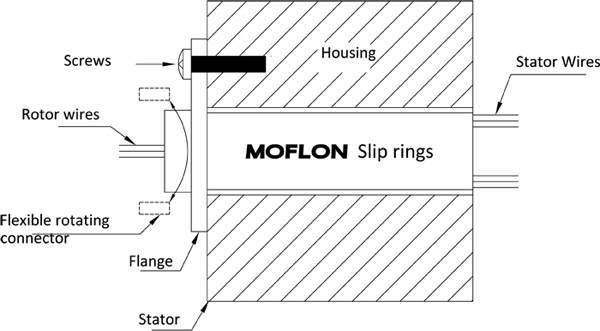
Flange Mounting Instructions
1. Align the mounting holes in the flange to mounting base and install flat washers and thread forming screws (NOT SUPPLIED) for plastic. Securely tighten screws.
2. Route the wiring and make the necessary connections. Do not allow the wiring to restrict free rotation of the slip ring.
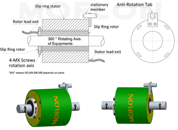
3. Position a screw or dowel (NOT SUPPLIED) in the anti-rotation tab to the dimension as shown.
CAUTION: Because of possible geometric mismatching between the customer��s application and the slip ring, 'hard mounting' of both ends of the slip ring (i.e., securing the rotor and stator such that there is NO floating during operation) is not recommended and may cause premature failure

Shaft Mounting Instructions(For Through bore style)
1.Main shaft mouted units:
A.Position the slip ring in the desired location and tighten both set screws to the shaft.Maximum torque 25Ib-in(DO NOT OVER TORQUE)
B.Route the wiring and make the neccessary connections.Do not allow the wiring to restrict free rotation of the slip ring.Do not constrain wiring such that wire flexing occurs.Doing so will ultimately cause failure(breakage of the wiring).
2.Housing mouted units:
A.Anti-Rotation tap used for connecting the stator of slip ring with the stationary member of euipment
B.Route the wiring and make the neccessary connections.Do not allow the wiring to restrict free rotation of the slip ring.

Typical Application
- CCTV Monitoring System.
- Electrical test equipment.
- Medical equipment.
- Rotary table
- Robotics
- Laboratory equipmen
- Manufacturing and process control equipment